- 您现在的位置:买卖IC网 > Sheet目录477 > MICRF220AYQS TR (Micrel Inc)RCVR ASK/OOK 300-450MHZ 16QSOP
�� �
�
�Micrel,� Inc.�
�Supply� Voltage� Ramping�
�When� supply� voltage� is� initially� applied,� it� should� rise�
�monotonically� from� 0V� to� 3.3V� to� ensure� proper� startup�
�of� the� crystal� oscillator� and� the� PLL.� It� should� not� have�
�multiple� bounces� across� 2.6V,� which� is� the� threshold� of�
�the� undervoltage� lockout� (UVLO)� circuit� inside�
�MICRF220.�
�Antenna� and� RF� Port� Connections�
�Figure� 8� shows� the� schematic� of� the� MICRF220�
�Evaluation� Board.� Figures� 9� thru� 11� depict� PCB� images.�
�This� evaluation� board� is� a� good� starting� point� for� the�
�prototyping� of� most� applications.� The� evaluation� board�
�offers� two� options� of� injecting� the� RF� input� signal:�
�through� a� PCB� antenna� or� through� a� 50� Ω� SMA�
�connector.� The� SMA� connection� allows� for� conductive�
�testing,� or� an� external� antenna.�
�Low-Noise� Amplifier� Input� Matching�
�Capacitor� C3� and� inductor� L2� form� the� “L”� shape� input�
�matching� network� to� the� SMA� connector.� The� capacitor�
�cancels� out� the� inductive� portion� of� the� net� impedance�
�after� the� shunt� inductor,� and� provides� additional�
�attenuation� for� low-frequency� outside� band� noise.� The�
�inductor� is� chosen� to� over� resonate� the� net� capacitance�
�at� the� pin,� leaving� a� net-positive� reactance� and�
�increasing� the� real� part� of� the� impedance.� It� also�
�provides� additional� ESD� protection� for� the� antenna� pin.�
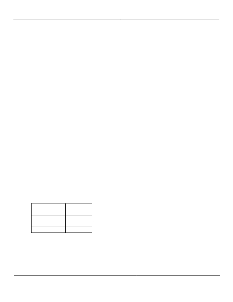
�The� input� impedance� of� the� device� is� listed� in� Table� 6� to�
�aid� calculation� of� matching� values.� Note� that� the� net�
�impedance� at� the� pin� is� easily� affected� by� component�
�pads� parasitic� due� to� the� high� input� impedance� of� the�
�device.� The� numbers� in� Table� 6� does� NOT� include� trace�
�and� component� pad� parasitic� capacitance,� which� total�
�about� 0.75pF� on� the� evaluation� board.�
�The� matching� components� to� the� PCB� antenna� (L3� and�
�C9)� were� empirically� derived� for� best� over-the-air�
�reception� range.�
�MICRF220�
�Crystal� Selection�
�The� crystal� resonator� provides� a� reference� clock� for� all�
�the� device� internal� circuits.� Crystal� tolerance� needs� to�
�be� chosen� such� that� the� down-converted� signal� is�
�always� inside� the� IF� bandwidth� of� MICRF220.� From� this�
�consideration,� the� tolerance� should� be� ±� 50ppm� on� both�
�the� transmitter� and� the� MICRF220� side.� ESR� should� be�
�less� than� 300� ?� ,� and� the� temperature� range� of� the� crystal�
�should� match� the� range� required� by� the� application.�
�With� the� Abracon� crystal� listed� in� the� Bill� of� Materials,� a�
�typical� MICRF220� crystal� oscillator� still� starts� up� at�
�105oC� with� additional� 400� ?� series� resistance.�
�The� oscillator� of� the� MICRF220� is� a� Pierce-type�
�oscillator.� Good� care� must� be� taken� when� laying� out� the�
�printed� circuit� board.� Avoid� long� traces� and� place� the�
�ground� plane� on� the� top� layer� close� to� the� REFOSC� pins�
�RO1� and� RO2.� When� care� is� not� taken� in� the� layout,� and�
�the� crystals� used� are� not� verified,� the� oscillator� may� not�
�start� or� takes� longer� to� start.� Time-to-good-data� will� be�
�longer� as� well.�
�PCB� Considerations� and� Layout�
�Figures� 9� thru� 11� illustrate� the� MICRF220� Evaluation�
�Board� layout.� The� Gerber� files� provided� are�
�downloadable� from� the� Micrel� website� and� contain� the�
�remaining� layers� needed� to� fabricate� this� board.� When�
�copying� or� making� one’s� own� boards,� make� the� traces�
�as� short� as� possible.� Long� traces� alter� the� matching�
�network� and� the� values� suggested� are� no� longer� valid.�
�Suggested� matching� values� may� vary� due� to� PCB�
�variations.� A� PCB� trace� 100� mils� (2.5mm)� long� has� about�
�1.1nH� inductance.� Optimization� should� always� be� done�
�with� exhaustive� range� tests.� Make� sure� the� individual�
�ground� connection� has� a� dedicated� via� rather� then�
�sharing� a� few� of� ground� points� by� a� single� via.� Sharing�
�ground� via� will� increase� the� ground� path� inductance.�
�Ground� plane� should� be� solid� and� with� no� sudden�
�interruptions.� Avoid� using� ground� plane� on� top� layer� next�
�to� the� matching� elements.� It� normally� adds� additional�
�stray� capacitance� which� changes� the� matching.� Do� not�
�Frequency� (MHz)�
�315�
�390�
�418�
�433.92�
�Z� Device� (� ?� )�
�23� ?� j290�
�14� –� j230�
�17� –� j216�
�12� –� j209�
�use� Phenolic� materials� as� they� are� conductive� above�
�200MHz.� Typically,� FR4� or� better� materials� are�
�recommended.� The� RF� path� should� be� as� straight� as�
�possible� to� avoid� loops� and� unnecessary� turns.�
�Separate� ground� and� V� DD� lines� from� other� digital� or�
�switching� power� circuits� (such� microcontroller…etc).�
�Known� sources� of� noise� should� be� laid� out� as� far� as�
�possible� from� the� RF� circuits.� Avoid� unnecessary� wide�
�Table� 6.� Input� Impedance� for� the� Most� Used� Frequencies�
�traces� which� would� add� more� distribution� capacitance�
�(between� top� trace� to� bottom� GND� plane)� and� alter� the�
�RF� parameters.�
�August� 2010�
�14�
�M9999-082610-A�
�发布紧急采购,3分钟左右您将得到回复。
相关PDF资料
MICRF221AYQS TR
IC RF RECEIVER QWIKRADIO 16-QSOP
MICRF300YC6 TR
IC AMP 100/1000MHZ LN SC70-6
MICRF500BLQTR
TXRX UHF 700-1100MHZ 44-LQFP
MICRF501BLQ TR
TXRX SGL 300-600MHZ 44-LQFP
MICRF505DEV1
KIT DEV RADIOWIRE 850-950MHZ
MICRF506DEV1
EVAL BOARD EXPERIMENTAL MICRF506
MICRF507YML TR
TXRX FSK LOW PWR W/AMP 32MLF
MICRF600DEV1
KIT DEV RADIOWIRE 902-928MHZ
相关代理商/技术参数
MICRF221
制造商:MICREL 制造商全称:Micrel Semiconductor 功能描述:3.3V, QwikRadio 850 MHz to 950 MHz Receiver
MICRF221AYQS
功能描述:射频接收器 850MHz to 950MHz, 3.0V to 3.6V, 9mA, 10kbps ASK Recdeiver with Auto-Poll and RSSI, Shutdown in 16-lead QSOP
RoHS:否 制造商:Skyworks Solutions, Inc. 类型:GPS Receiver 封装 / 箱体:QFN-24 工作频率:4.092 MHz 工作电源电压:3.3 V 封装:Reel
MICRF221AYQS TR
功能描述:射频接收器 850MHz to 950MHz, 3.0V to 3.6V, 9mA, 10kbps ASK Recdeiver with Auto-Poll and RSSI, Shutdown in 16-lead QSOP
RoHS:否 制造商:Skyworks Solutions, Inc. 类型:GPS Receiver 封装 / 箱体:QFN-24 工作频率:4.092 MHz 工作电源电压:3.3 V 封装:Reel
MICRF229YQS-T5
功能描述:- RF Receiver ISM 433.92MHz -112dBm 20kbps On-Board, Trace 16-QSOP 制造商:microchip technology 系列:- 包装:剪切带(CT) 零件状态:停产 频率:433.92MHz 灵敏度:-112dBm 数据速率(最大值):20kbps 调制或协议:ISM 应用:通用 电流 - 接收:6mA 数据接口:- 存储容量:- 天线连接器:板载,跟踪 特性:- 电压 - 电源:3.5 V ~ 5.5 V 工作温度:-40°C ~ 105°C 封装/外壳:16-LSSOP(0.154",3.90mm 宽) 供应商器件封装:16-QSOP 标准包装:1
MICRF229YQS-TR
功能描述:- RF Receiver ISM 433.92MHz -112dBm 20kbps On-Board, Trace 16-QSOP 制造商:microchip technology 系列:- 包装:剪切带(CT) 零件状态:停产 频率:433.92MHz 灵敏度:-112dBm 数据速率(最大值):20kbps 调制或协议:ISM 应用:通用 电流 - 接收:6mA 数据接口:- 存储容量:- 天线连接器:板载,跟踪 特性:- 电压 - 电源:3.5 V ~ 5.5 V 工作温度:-40°C ~ 105°C 封装/外壳:16-LSSOP(0.154",3.90mm 宽) 供应商器件封装:16-QSOP 标准包装:1
MICRF230YQS-T5
功能描述:- RF Receiver ISM 433.92MHz -112dBm 20kbps On-Board, Trace 16-QSOP 制造商:microchip technology 系列:- 包装:剪切带(CT) 零件状态:停产 频率:433.92MHz 灵敏度:-112dBm 数据速率(最大值):20kbps 调制或协议:ISM 应用:通用 电流 - 接收:6mA 数据接口:- 存储容量:- 天线连接器:板载,跟踪 特性:- 电压 - 电源:3.5 V ~ 5.5 V 工作温度:-40°C ~ 105°C 封装/外壳:16-LSSOP(0.154",3.90mm 宽) 供应商器件封装:16-QSOP 标准包装:1
MICRF230YQS-TR
功能描述:- RF Receiver ISM 433.92MHz -112dBm 20kbps On-Board, Trace 16-QSOP 制造商:microchip technology 系列:- 包装:剪切带(CT) 零件状态:有效 频率:433.92MHz 灵敏度:-112dBm 数据速率(最大值):20kbps 调制或协议:ISM 应用:通用 电流 - 接收:6mA 数据接口:- 存储容量:- 天线连接器:板载,跟踪 特性:- 电压 - 电源:3.5 V ~ 5.5 V 工作温度:-40°C ~ 105°C 封装/外壳:16-LSSOP(0.154",3.90mm 宽) 供应商器件封装:16-QSOP 标准包装:1
MICRF300-315 EV
功能描述:EVAL BOARD FOR MICRF300 制造商:microchip technology 系列:- 零件状态:无货 类型:放大器 频率:315MHz 配套使用产品/相关产品:MICRF300 所含物品:板 标准包装:1